C++, OpenCV, OpenGL, Tesseract
For the software component of my capstone project, G-Code Workbench is an interactive program for configuring and executing path-generating algorithms for the accompanying CNC plotter as well as my other homemade CNC projects.
See the hardware component of this project here
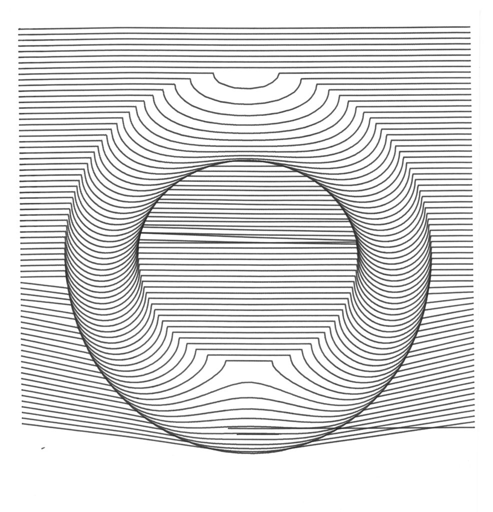
Wave art
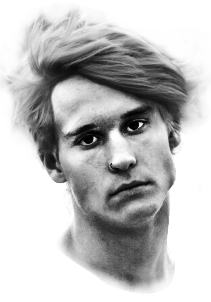
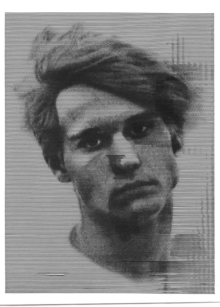
Taking inspiration from similar examples found online, I created two algorithms that can take photographs and shade them using a series of waves, or one spiraling wave. This process involves using multiple GLSL shaders to both average groups of pixel values, as well as to visualize the result of the algorithm parameters to create an efficient, real-time preview with hardware acceleration.
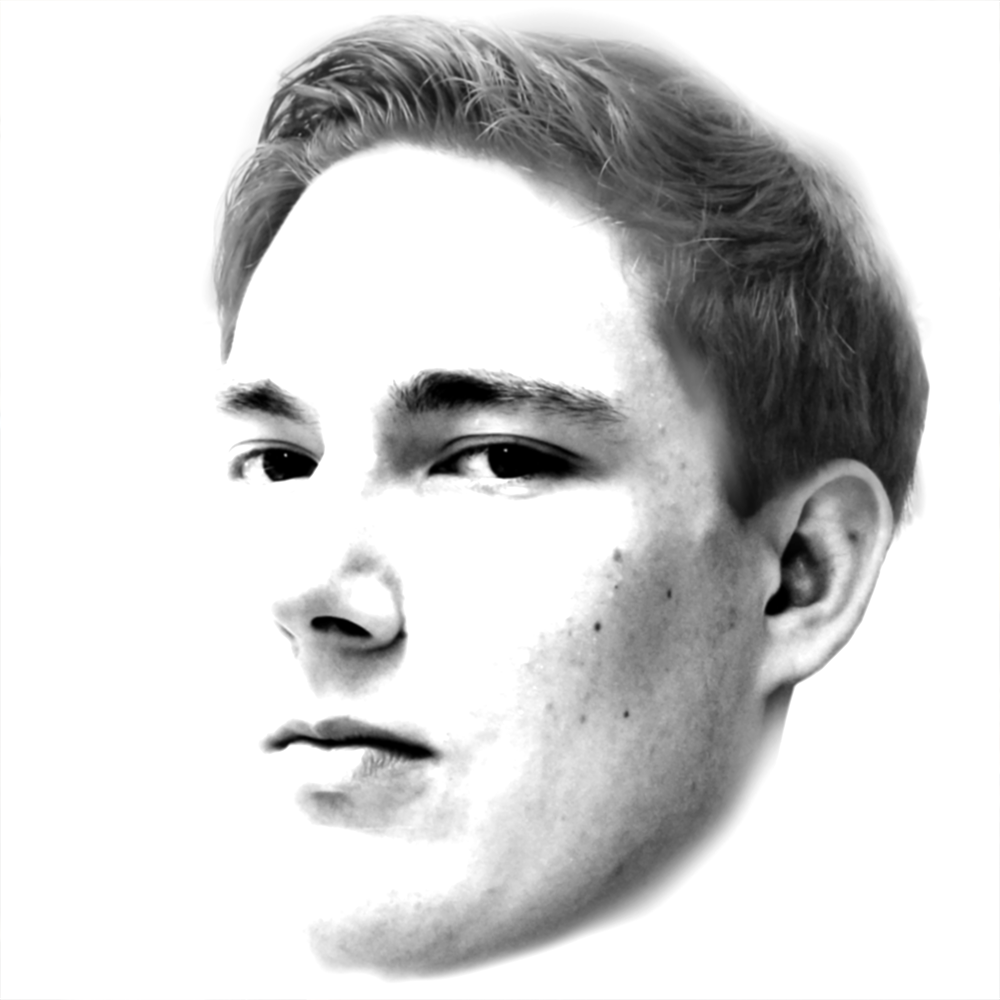
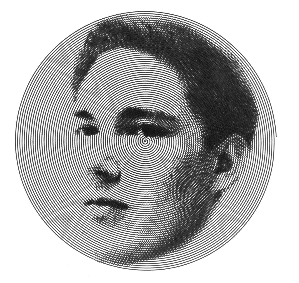
The generators work best with portraits because the human brain is especially good at detecting facial features. That being said, the images used still had to be heavily pre-processed to come out clearly. This could very well be automated or made as a built-in process using OpenCV or GLSL shaders.
Document scanning / Image stitching
The G-Code workbench not only generates G-Code but can also stream the data to the CNC drawbot and interface with its camera.
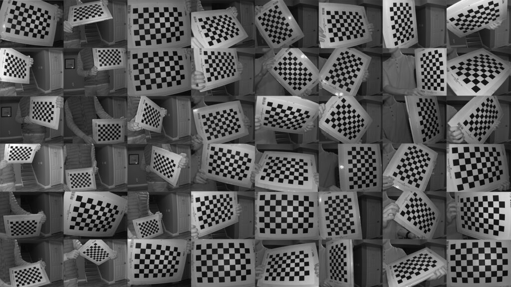
Unfortunately, the use of a wide-angle lens and proximity to the surface introduced too much distortion to be useful. To solve this I used OpenCV to create a lens distortion profile by taking a variety of photos of a checkerboard pattern.
Using the high-level stitching utilities in OpenCV to combine multiple corrected images of a surface was not possible. This is because the algorithms rely on distinct features. A common item to scan is paper which means there can be multiple images with nothing but white pixels. The repeating pattern caused by the LEDs attached to the camera also caused issues.
To solve this I used the physical CNC position data to get the relative positions of the images. The software combines the images with several parameters including image spacing, position offsets, stretching, feathering, and skewing. To get real-time feedback for these parameter adjustments, the images are combined using an OpenGL shader.
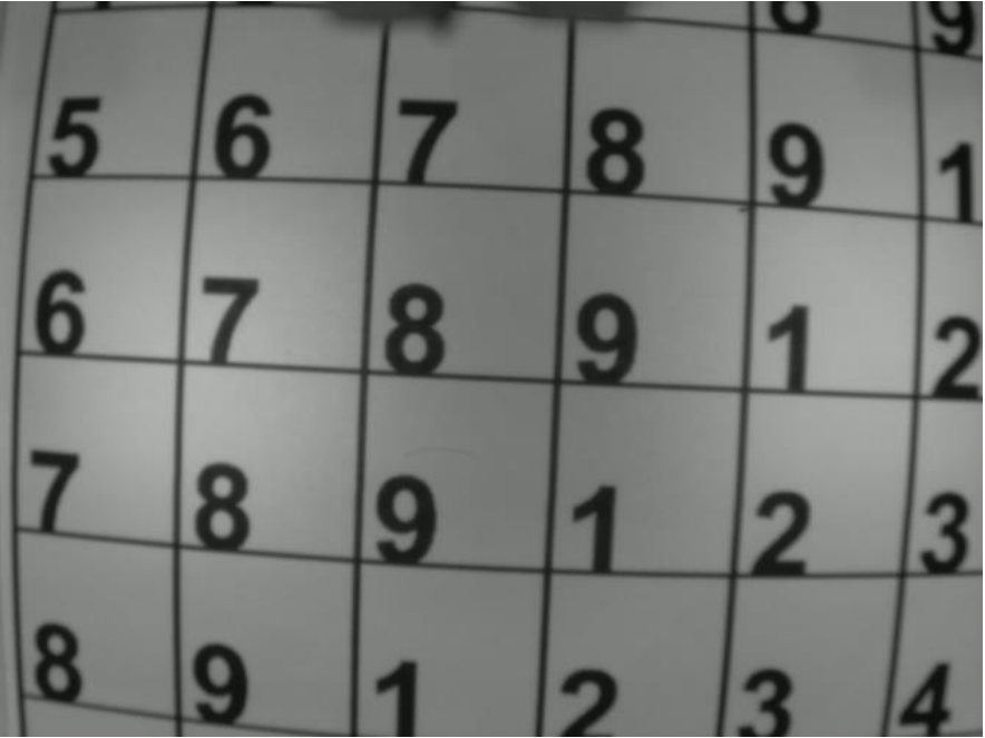
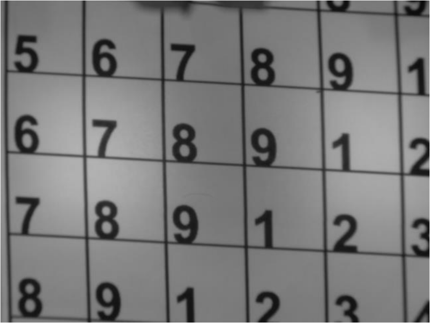
Word Search Solver
When running the world search solver, you can simply place the puzzle under the drawbot’s work area and it will solve it without any human input.
To actually “read” the puzzle I used Tesseract, which is an open-source optical character recognition
library with a pre-trained English character neural network.
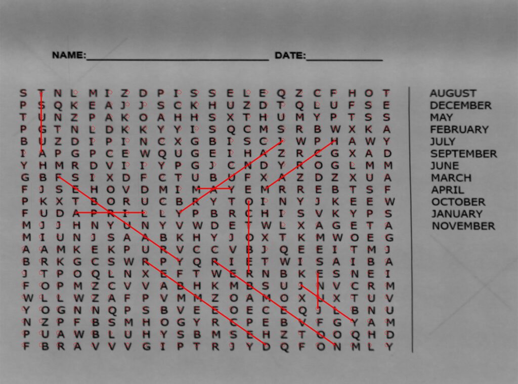
With all of the data from the puzzle extracted, I just needed to write a simple script to search for the solution in the matrix of letters.
Next, the solution is physically drawn onto the puzzle using lines. This step is accomplished using a
physical pixel mapping technique described in 5.3.2 in the technical report, which can convert pixel locations on the stitched image to absolute locations the drawbot can position the pen.
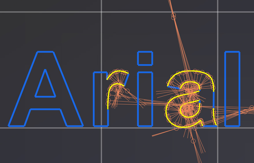
Font Tracing
To draw letters, I used STB Truetype to extract curve information from any font file in the form of a series of straight lines and quadratic Bezier curves.
Since G-Code can only take the form of circular arc segments, my algorithm efficiently approximates the Bezier curves as arc segments which can be subdivided for additional accuracy.
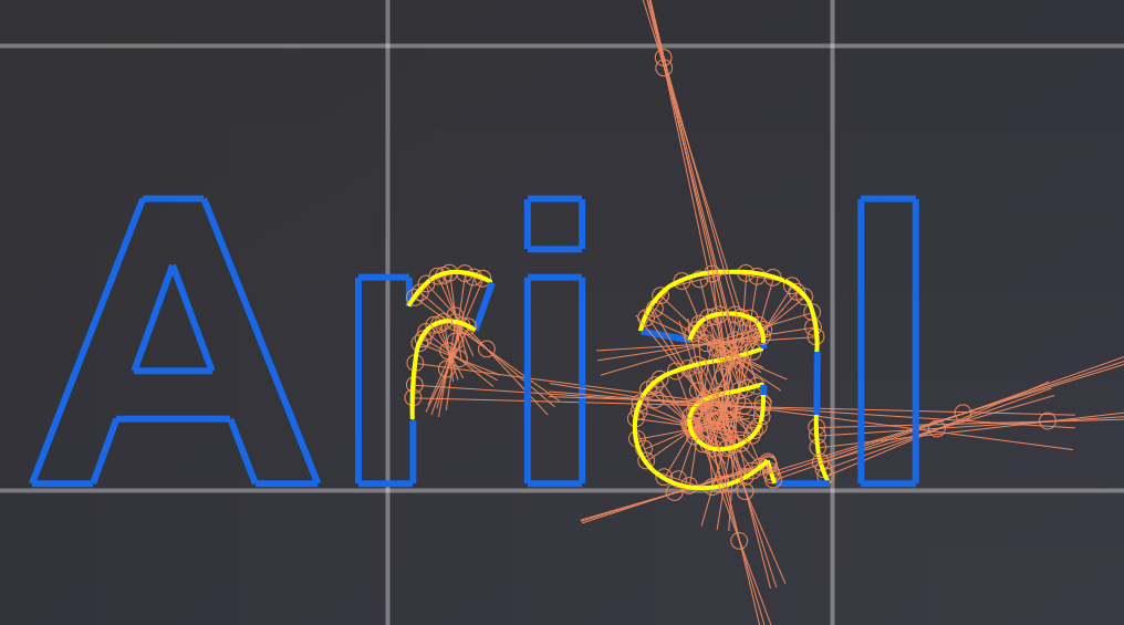

The software can also stream letter paths to the drawbot as you are typing on the keyboard like a typewriter!
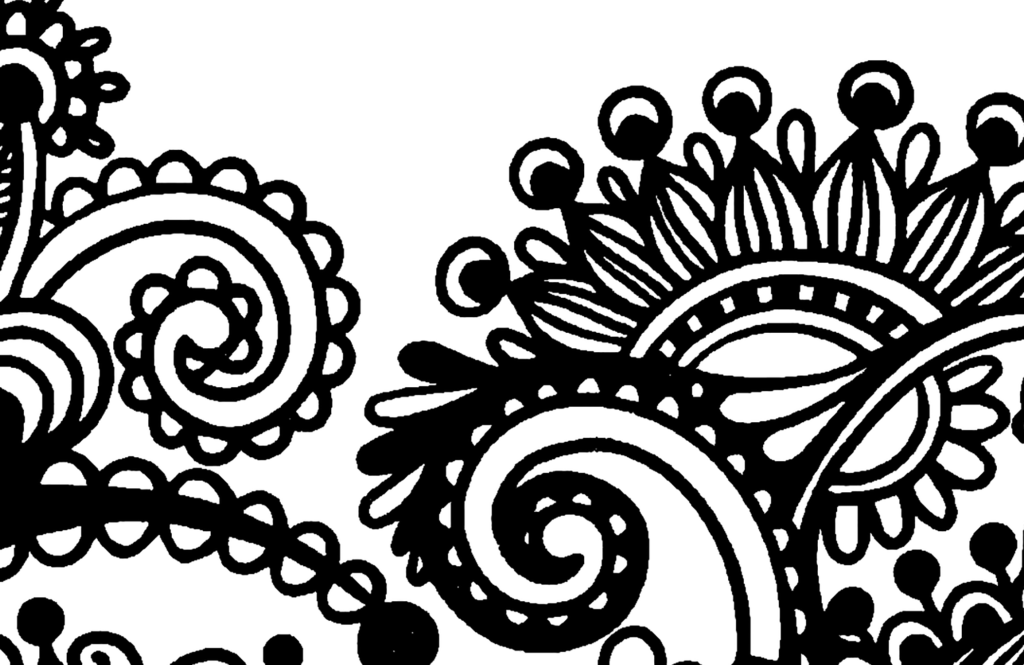
Vector Tracing
To create silhouette paths of clipart, I used the contour detection features of the OpenCV library. The OpenCV functions return a series of line loops that outline the image. This lets me combine the process with the rectilinear infill algorithm described below to fill in solid sections of an image in addition to simply tracing it.
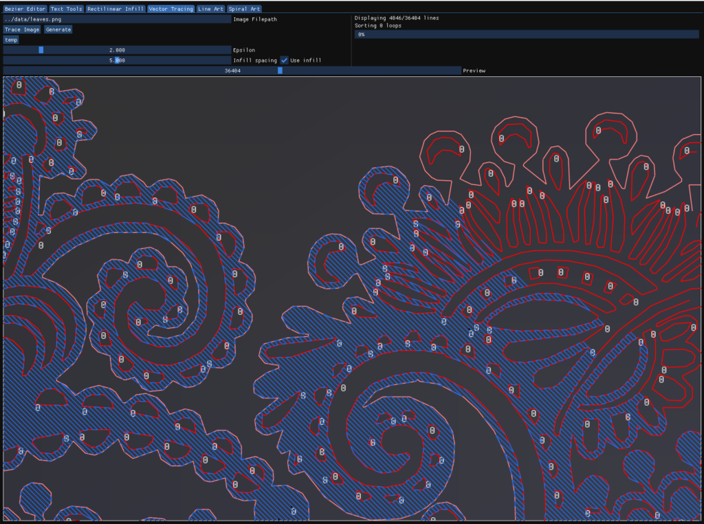
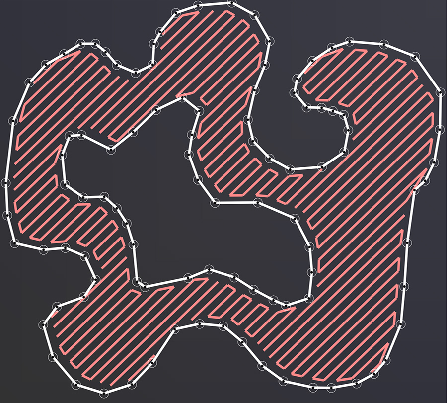
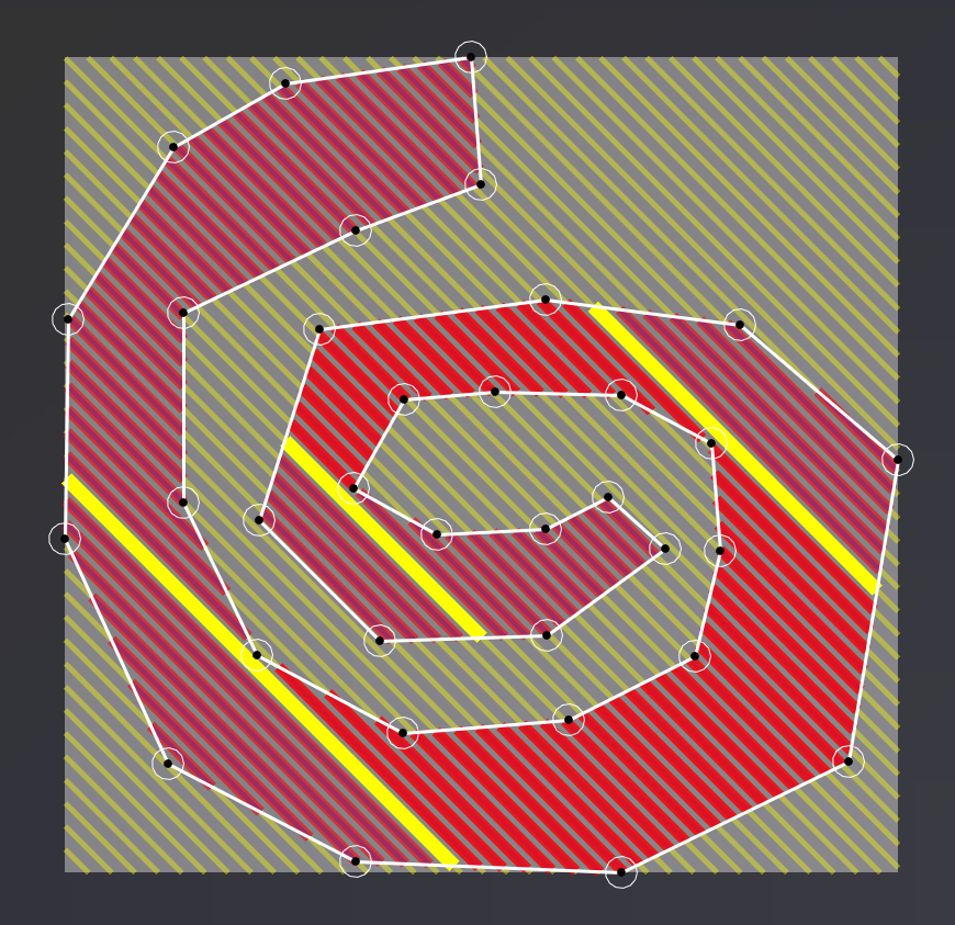
Rectilinear Infill
To “fill in” the polygons created by vector/font tracing I need to generate a series of paths that can efficiently cover the entire area of the polygons created by the letters.
To do this I created a rectilinear infill generation algorithm completely from scratch. It works similar to how a 3D printer might cover a surface on a solid top layer. The algorithm has parameters for pen width, infill padding, line angle, and more. It’s also very fast, connecting all the lines with reasonable movement optimization without any permutation in the algorithm.
3D Model Representation
Similar to the wave art features, you can load a simple 3D Model into the workbench and shade it with pen paths. The tricky aspect of this feature is how an internal shader renders the model as a depth map. From there, lines are simply drawn with the height corresponding to the model’s depth with some post-processing to fix intersecting lines around sharp edges.
The final result of the above demo has some errors because this was a bonus feature I added with the extra time in my semester and I ran out before fixing all the bugs with the path optimizer.
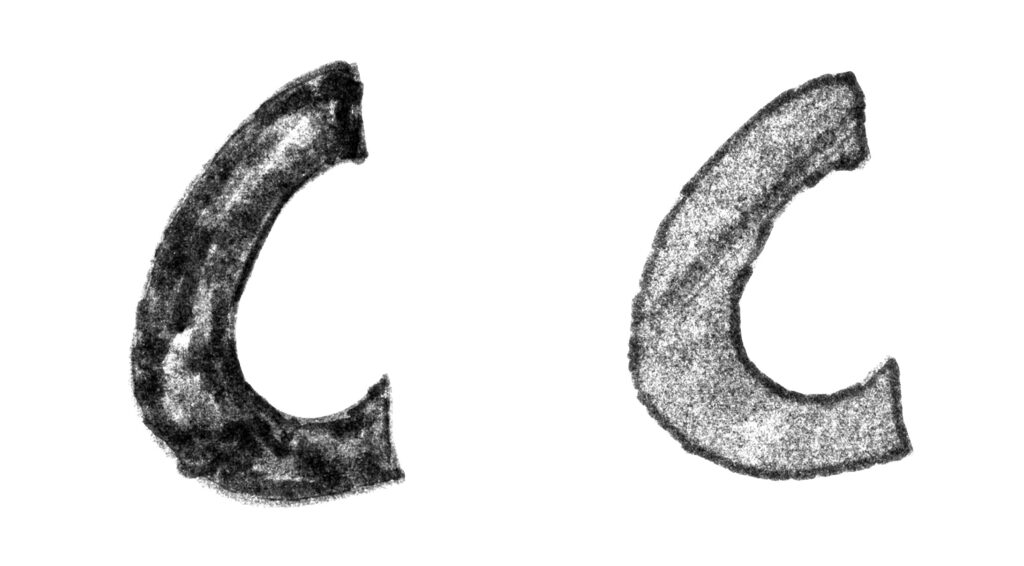
Drawing Replication
One of the features of the workbench is essentially a “photocopier mode”. This just uses a combination of the algorithms detailed above. A pixel position mapping algorithm was also created for this to work which is detailed at 5.3.2 in the technical report.
To replicate a hand-drawn image, the page is first scanned by the machine using the stitching algorithm. then, a gaussian blur and binary threshold is applied. Next, the vector tracing algorithm is run on the image. The resulting set of vector loops is then passed on to the infill algorithm. This set of paths is converted to a single G-Code script which can be run.
With a contrast curve applied, you can see the difference in how I used the marker to create the shape
compared to the rectilinear pattern used by the drawbot.